Investigation for Tunnel
• Tunnel is a nearly horizontal underground passage which is open at both ends.
• Tunnels are of different types according to their uses like traffic tunnel, hydropower headrace tunnel and public utility tunnels etc.
• Tunnels can be driven or holed through a rock or earth mass by method used in mining, including blasting.
• In soft ground tunnels may be excavated by boring machines with the walls being supported by liner plates.
Terminology
• Portal: opening of the tunnel
• Roof: top of tunnel
• Floor: bottom
• Face: surface exposed by excavation at the end of tunnel.
• Over break: rock excavated beyond the required cross-section.
• Support: structure erected in the tunnel bore after blasting.
• Lining: casings or sand and cement spray applied to the roof and sides to give support as well as smooth surface.
• Geology is the most important factor that determines the nature, form and cost of a tunnel.
• Tunnelling is an uncertain, often hazardous undertaking because information on ground conditions along alignment is never complete, no matter how good the site investigation.
• Estimating the cost of tunnel construction, particularly in area of geological complexity, is also uncertain.
• The basic geological document used in tunnel design is a geological profile along the centre line of tunnel.
• This profile should show the different type of rocks and soils along the tunnel line, boundaries between them (contacts) and geological defects such as fault.
• This document is accompanied by surface geological map which shows different formations, and structural features and any unusual water occurrences such as seeps and springs.
• Prior to tunnel construction, the subsurface geology may be explored by means of pits, adits, drills and pilot tunnels.
• A pilot tunnel is probably the best method of exploring tunnel locations and should be used if a major sized tunnel is to be constructed in a critical geological condition.
• Reliable information about the ground condition ahead of the advancing face is obtained by drilling long, horizontal holes from the tunnel face at regular intervals.
• In extremely poor ground condition, tunnel progresses behind an array of probe holes which fan outward some 10 to 30 m ahead of the tunnel face.
• These holes drilled upwards from the crown of the tunnel and forwards from the side walls help locate features such as faults, buried channels, weak seams or solution cavities.
• The inclination of these holes should be surveyed as maintaining the position of the hole may be a problem during horizontal drilling
• Geophysical investigation can give valuable assistance in determination of subsurface conditions.
• Seismic refraction has been used in measuring the depth of overburden in the portal areas of tunnels, in locating faults, weathered zones or buried channels and estimating rock quality.
• The seismic profiling is done along the proposed tunnel alignment and also in the drill holes.
• Resistivity survey has proved useful in locating water tables and buried faults which is a valuable information before tunnelling.
• Detailed engineering geological mapping of the alignment and portal areas are required before the actual start of the tunnelling.
• Tunnelling in hard rocks is more favourable than into the soft rocks as shale, slate, phyllites.
• Tunnelling in soft soil and rock create problem of support as well as squeezing and swelling.
• The difficulties and costs of construction with soft ground tunnelling depend almost exclusively on the stand up time of the ground and this in turn is influenced by the position of the water table in relation to the tunnel.
• In ravelling ground, blocks fall from the roof and sides of the tunnel some time after the ground exposed.
• Stiff clay with low plasticity have sufficient shearing and tensile strength to allow the tunnel with support above the water table.
• Rocks at depth are affected by the weight of the overburden and the stresses so developed cause the rock to be strained.
• While the rock remain in a confined condition the stresses may accumulate and when the confined condition is removed, as in tunnelling, then this stress can cause displacement.
• The pressure relief may be instantaneous or slow in character, and is accompanied by movement of the rock mass with variable degrees of violence.
• In tunnel driven at more depths, rock may suddenly break form the sides of the excavation, a phenomenon known as rock bursting.
• Rock burst are due to dissipation of residual stresses which exceed the strength of the ground around excavation and their frequency and severity increase with depth with most of them occurring at depth of more than 600 m.
• The tunnelling process is largely influenced by the geological structures of the rocks encountered.
• Tunnelling in horizontal bed is more favourable as pressure is distributed in all direction in case of horizontal bed unlike the inclined bed where the pressure concentration is at one side.
• When the joints spacing in horizontally layerd rocks is greater than the width of a tunnel, the beds bridge the tunnel as a solid slab and are only subject to bending under their own weight.
• When horizontal lying rocks are thickly bedded, the roof is flat.
• But in thin bedded horizontal strata, the overbreak will cause a peaked roof.
• The probable maximum overbreak is 0.5 times the breadth of the tunnel.
• Tunnels driven parallel to the strike of the layered rocks encounter serious problems of instability and seepage, particularly if the beds are steeply dipping or if alternation of hard and soft rock.
• When tunnel is driven across the strike, it will traverse beds of different rocks.
• In such case there will be downward pressure from the roof.
• When porous beds are encountered, groundwater problems may arise.
• If the joints are closely spaced, water may drain very easily into the excavation.
• Joints which are parallel to the axis of a tunnel and which dip more than 45 degrees may prove unstable, leading to slabbing of the wall and fallouts from roof which can be treated with rock bolting.
• Location of tunnel in an anticline is not recommended due to the stressed condition of rock in the hinge area.
• Tunnels in the anticline tends to relieve the vertical pressure on the lining whereas pressure increases in case of syncline.
• If water bearing strata is encountered in the syncline then the water tends to flow into the tunnel.
• Consideration should be given to the to the fact that in an anticline, the upper strata are more bent and hence more fissured by tensile stresses than the lower strata.
• Presence of faults in the tunnel alignment can be investigated by geological investigation of the surface geology as well as by using geo physical methods, so that prior knowledge of these shear zones can be obtained before the design of tunnel.
• Faults generally mean non-uniform rock pressure on a tunnel and hence at times necessitate special treatments.
• Generally problem increase as the strike of the fault becomes more parallel to the tunnel alignment.
• If the tunnel is driven from the hanging wall, the fault appears at the invert and it is generally possible to provide adequate support or reinforcements when driving through the rest of the zone.
• Conversely when a tunnel is driven from the foot wall side, the fault first appears in the crown, and there is a possibility that a wedge-shaped block, formed by the fault and the tunnel, will fail form the roof without warning.
• Major faults are usually associated with number of minor faults and shear zones over many metres.
• Rock material in these shear zones are shattered and are brecciated and occupied by gouge.
• Through these shear zones water may flow into the tunnel as they are easy passageway for groundwater.
• The clay gouge of the shear zone may swell and cause displacement or breakage of tunnel supports in extreme cases.
• Movement along major active faults zones can disrupt a tunnel lining and even lead to offset of tunnel.
• Earthquake risk to an underground structure is influenced by the material in which it occurs.
• In a shallow depth tunnel in alluvial deposit, the tunnel may be hampered during earthquake by the large relative displacement of the ground surrounding it.
• On the other hand, a deep tunnel, in solid rock will be subjected to the displacement which are considerably less than those which occur at the surface.
• The main cause of stresses in shallow structures arise form the interaction between the structure and the displacements of the ground.
• If the structure is sufficiently flexible it will follow the displacements and deformations to which the ground is subjected.
• Construction of tunnel may alter the groundwater regime of a locality, as a tunnel generally acts as a drain.
• Large quantity of water flow is unfavourable.
• Proper drainage, compressed air, grouting or freezing techniques can be applied for minimising the effect.
• Gas are produced during blasting in the tunnel.
• Tunnels being underground are generally devoid of oxygen and presence of toxic gases increase the problem.
• So proper aeration or ventilation of tunnels is a must.
• Temperature inside the earth rises at the rate of 1 degree Celsius every 35 m.
• So temperature inside the tunnel may be a few degrees above that of the surface.
• Proper ventilation of the tunnel reduces the problem caused by temperature if any.
• Location of tunnel entrance or portal should be free of any slope instabilities.
• Damping site for muck should be identified near the portal.
• Effects of tunnelling groundwater fluctuation and subsidence of ground should be noted.
• The time a rock mass may remain unsupported in a tunnel is called its stand-up time.
• This mainly depends on the magnitude of the stresses within the unsupported rock mass, which in their turn depend on its span, strength and discontinuity pattern.
• The primary support for a tunnel in rock masses excavated by drilling and blasting, in particular, may be provided by wire mesh, rock bolts (with or without reinforcing wire mesh), shotcrete or steel arches or ribs.
• A classification of rock masses is of primary importance in relation to the design of the type of tunnel support.
• Bieniawski (1974, 1989) maintained that the uniaxial compressive strength of rock material; the rock quality designation; the spacing, orientation and condition of the discontinuities; and groundwater inflow were the factors that should be considered in any engineering classification of rock masses.
Geological documentation during tunnelling
• During excavation, there are many documents to be prepared and recorded.
• Before any new excavation cycle is started, a method statement should be prepared by the engineering geologist.
• It includes detail about principal equipments used, methodology and detail schedule of that excavation method or cycle.
• The log of probe drilling is kept to know what material will be encountered during tunnel advance.
• Apart from that, a lab report of strength of shotcrete is also needed.
• This report has to be prepared before using the shotcrete.
• After excavation, the tunnel may converge due to release of stress.
• This convergence may be very small which could be neglected but in some cases this may be of large value.
• The convergence is documented in a monitoring points or convergence station at certain interval of the tunnel length.
• A face map or tunnel geological map is another important document.
• It shows the geology of the face, wall and crown of the tunnel after every excavation.
• It includes the rock strength, rock type, an engineering geological map of the tunnel and recommendation for the support class.
• This face map later is joined to develop a complete and detailed engineering geological map or as-built-map of the tunnel.
• In the final geological map and report accompanying it, the basic differences between the prediction of the preliminary report and what was actually found during construction is thoroughly explained.
• This log may prove of considerable value if unusual maintenance problems develop in given tunnel or if another tunnel in the vicinity is planned.
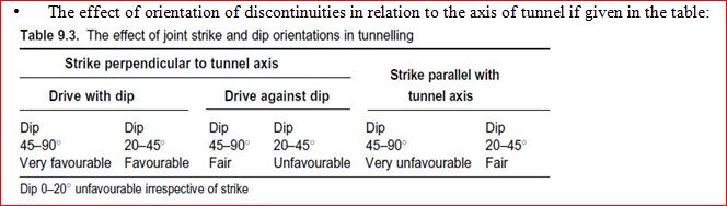
Effect of orientation of discontinuities in relation to axis of tunnel
